Learning to program FPGA's
About two months ago a couple of guys from Labitat (including myself) decided to meet up every other week for an FPGA playpen.
I have worked a little with FPGA’s back when I was studying at the university, but have since forgotten most of it, so I will be starting out with the basics and slowly move on to more advanced aspects of designing logic for FPGA’s.
The first couple of times was used to get everything set-up (I’m using a Mac, so this involves a virtual machine running Windows 7 32Bit) and getting a super simple “Hello world” design implemented and running.
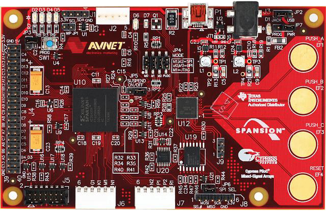
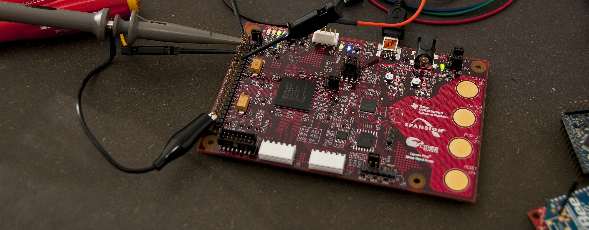
I’m using the AVNET Xilinx® Spartan®-3A Evaluation Kit, which in addition to a Spartan 3A FPGA, uses a Cypress PSoC as the USB programming interface, and both serial and parallel flash from Spansion. The board is fairly simplistic - there are not a lot of interface connectors or displays - only 4 diodes for testing output, 4 capacitive touch buttons wired via the PSoC to the FPGA and a tiny I2C temperature sensor from Texas Instruments.
The kit includes a regular USB cable and MiniProg programming unit for the Cypress PSoC in case you need to update the firmware (I did) or simply want to play around with the PSoC.
“Hello World” design in VHDL
The first implementation is from the “ISE FPGA Design Introduction” available at the AVNET Resource Center.
The guide is written for Xilinx ISE 10.1, but the major parts are almost identical with the newer 12.1 release of the free Xilinx ISE Webpack.
library IEEE;
use IEEE.STD_LOGIC_1164.ALL;
use IEEE.STD_LOGIC_ARITH.ALL;
use IEEE.STD_LOGIC_UNSIGNED.ALL;

entity simple_count is
    Port ( clock : in  STD_LOGIC;
           enable : in  STD_LOGIC;
           leds : out  STD_LOGIC_VECTOR (3 downto 0));
end simple_count;

architecture Behavioral of simple_count is

signal count: std_logic_vector (3 downto 0) := "0000";

begin

process (clock)
begin
   if clock='1' and clock'event then
		if enable='1' then
			count <= count + 1;
		end if;
   end if;
end process;

leds <= count(3 downto 0);

end Behavioral;
In the above design, the ‘clock’ is connected to the 16MHz clock input on the FPGA, the ‘enable’ is connected to button 1, and the ‘leds’ bus is connected to the 4 LEDs on the board. The UCF file for use with the AVNET Xilinx® Spartan®-3A Evaluation Kit is listed below.
NET "clock" TNM_NET = clock;
TIMESPEC TS_clock = PERIOD "clock" 62.5 ns HIGH 50%;

NET "clock" LOC = C10;
NET "enable" LOC = K3;
NET "leds<0>" LOC = D14;
NET "leds<1>" LOC = C16;
NET "leds<2>" LOC = B14;
NET "leds<3>" LOC = D13;

NET "clock" IOSTANDARD = "LVCMOS33";
NET "enable" IOSTANDARD = "LVCMOS33";
NET "leds<0>" IOSTANDARD = "LVCMOS33";
NET "leds<1>" IOSTANDARD = "LVCMOS33";
NET "leds<2>" IOSTANDARD = "LVCMOS33";
NET "leds<3>" IOSTANDARD = "LVCMOS33"
When you press button 1, the counter will be incremented and the LEDs will flash very quickly. When you release button 1, ‘enable’ will go low and the counter will stop being incremented. This will result in the LEDs showing the counter value from when the button was released.
It’s a very simple design, but what I like about it is that even as a beginner, it’s possible to understand all the steps involved. Next time we will go a little further, but still keep it as simple as possible.