This time, we will look at how to control a regular RC hobby servo. They come in many different sizes and gearings, but for the basic control, they all use a simple PWM (Pulse Width Modulation) signal, to indicate the desired position.
The width of the pulse should be between 1000 and 2000µs, with 1500µs representing the center position. Some brands have slight differences as to where the center point is, and some also allow pulses to be smaller than 1000µs and larger than 2000µs, but you can’t count on that. You also need to send a pulse to the servo at least every 20ms, otherwise the servo will likely enter standby, and it will no longer hold it’s position if there is a load on the arm.
The implementation below is loosely based on the design described at fpga4fun.com, but instead of Verilog, I have decided to use VHDL.
In addition to controlling the servo, I have tried to separate the project into multiple entities, as a preparation to expand with other controls.
Servo Driver
First we have the VHDL code to implement the servo driver. It has an input for the clock signal and an 8bit vector for the position. On the output side, it has a single output for the servo control line.
1 2 3 4 5 6 7 8 9 10 11 12 13 14 15 16 17 18 19 20 21 22 23 24 25 26 27 28 29 30 31 32 33 34 35 36 37 38 39 40 41 42 43 44 45 46 47 48 49 50 51 52 53 54 | library IEEE; use IEEE.STD_LOGIC_1164.ALL; use IEEE.STD_LOGIC_ARITH.ALL; use IEEE.NUMERIC_STD.ALL; use IEEE.STD_LOGIC_UNSIGNED.ALL; entity ServoDriver is Port ( Clk : in STD_LOGIC; Position : in STD_LOGIC_VECTOR (7 downto 0); Servo : out STD_LOGIC); end ServoDriver; architecture Behavioral of ServoDriver is constant ClockDiv: integer := 63; signal ClockTick: std_logic := '0'; signal ClockCount: std_logic_vector (6 downto 0) := "0000000"; signal PulseCount: std_logic_vector (11 downto 0) := "000000000000"; begin process (Clk) begin if Clk='1' and Clk'event then if ClockCount = ClockDiv-2 then ClockTick <= '1'; else ClockTick <= '0'; end if; if ClockTick='1' then ClockCount <= "0000000"; else ClockCount <= ClockCount + 1; end if; end if; end process; process (Clk) begin if Clk='1' and Clk'event then if ClockTick='1' then PulseCount <= PulseCount + 1; end if; if PulseCount < ("0001" & Position) then Servo <= '1'; else Servo <= '0'; end if; end if; end process; end Behavioral; |
Button controller
To test out the ServoDriver above, I made a little entity, that uses button presses to increment and decrement a counter. It’s fairly simple, the most tricky part is the conversions, to make sure it’s running unsigned all the time, especially when the 8bit ServoPos signal is wrapping around.
1 2 3 4 5 6 7 8 9 10 11 12 13 14 15 16 17 18 19 20 21 22 23 24 25 26 27 28 29 30 31 32 33 34 35 36 37 38 | library IEEE; use IEEE.STD_LOGIC_1164.ALL; use IEEE.STD_LOGIC_ARITH.ALL; use IEEE.NUMERIC_STD.ALL; use IEEE.STD_LOGIC_UNSIGNED.ALL; entity Controller is Port ( ButtonDown : in STD_LOGIC; ButtonUp : in STD_LOGIC; Position : out STD_LOGIC_VECTOR (7 downto 0)); end Controller; architecture Behavioral of Controller is signal ServoPos: unsigned(7 downto 0) := "00000000"; signal Button: std_logic; signal Direction: std_logic; begin process (Button) begin if Button='1' and Button'event then if Direction='1' then ServoPos <= ServoPos + 4; Position <= conv_std_logic_vector(ServoPos, 8); else ServoPos <= ServoPos - 4; Position <= conv_std_logic_vector(ServoPos, 8); end if; end if; end process; Button <= ButtonDown xor ButtonUp; Direction <= ButtonUp and not ButtonDown; end Behavioral; |
Top module
Finally, I made an entity to connect the Controller with the ServoDriver. It makes two instances, one of each entity, and has an 8bit signal (Position) between the two.
1 2 3 4 5 6 7 8 9 10 11 12 13 14 15 16 17 18 19 20 21 22 23 | library IEEE; use IEEE.STD_LOGIC_1164.ALL; use IEEE.STD_LOGIC_ARITH.ALL; use IEEE.NUMERIC_STD.ALL; use IEEE.STD_LOGIC_UNSIGNED.ALL; entity ServoUpDown is Port ( Clk : in STD_LOGIC; ButtonUp : in STD_LOGIC; ButtonDown : in STD_LOGIC; Servo : out STD_LOGIC); end ServoUpDown; architecture Behavioral of ServoUpDown is signal Position : std_logic_vector (7 downto 0); begin Servo1: entity ServoDriver port map (Clk, Position, Servo); Controller1: entity Controller port map (ButtonDown, ButtonUp, Position);
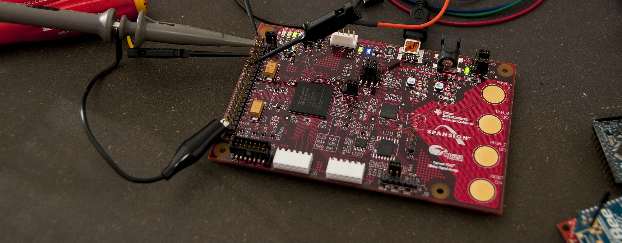
 end Behavioral; |
UCF file for the AVNET Xilinx® Spartan®-3A Evaluation Kit
I’m using the following UCF file to connect the above with the outside world. The servo has the negative lead connected to GND on the board, positive to +5v, and the signal wire connected to D10. The two buttons are PUSH_A and PUSH_B on the board, connected via the PSoC.
1 2 3 4 5 6 7 8 9 10 11 12 13 14 15 | #Created by Constraints Editor (xc3s400a-ft256-4) - 2010/06/17 NET "Clk" TNM_NET = "Clk"; TIMESPEC TS_Clk = PERIOD "Clk" 62.5 ns HIGH 50 %; # PlanAhead Generated physical constraints NET "Clk" LOC = C10; NET "ButtonUp" LOC = K3; NET "ButtonDown" LOC = H5; NET "Servo" LOC = D10; # PlanAhead Generated IO constraints NET "Clk" IOSTANDARD = LVCMOS33; NET "ButtonUp" IOSTANDARD = LVCMOS33; NET "ButtonDown" IOSTANDARD = LVCMOS33;
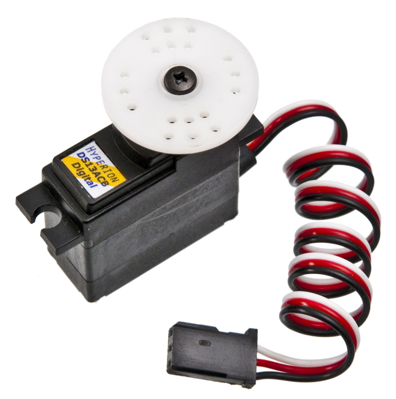
 NET "Servo" IOSTANDARD = LVCMOS33; |
The servo should ideally use 5v logic for the signal, but many servos will accept a 3.3v signal without any problems including the Hyperion Atlas Digital servo I’m using (HP-DS13-ACB).
Below is a short video showing the servo move as the buttons are pressed.
Related posts:
- Using a quadrature encoder as input to FPGA This time, instead of using buttons to control the servo,...
- Learning to program FPGA’s About two months ago a couple of guys from Labitat...
- Alternative programming cable for LCD I/O Backpack Following up with yet another alternative to the FTDI cable...
Hey there,
Great vhdl code I have used these ideas to control a servo for a project. I have a question to ask though, I was wondering how the std_logic_vector works for the clock divider…I am puzzled as to how a count up to 64 (in your first code) can divide a clock all the way down to 50Hz? Thanks in advance.
Hi Kyle,
It’s not going all the way down to ~50Hz with that counter, it only divides down to about 250kHz, which is the smalles variation in pulse width possible, and then uses the overflow on PulseCount to start the next pulse, which ends up a little more often than 50Hz (closer to 62Hz), but most, if not all servos can accept pulses much quicker often up to almost 400Hz.
/Thomas
hello thomas.i have a project like yours.According to my project i have to control servo motors angle and speed.I think i can write a code like yours for speed but do you have an idea for angle control code??
The angle of the servo is controlled by the width of the pulse or in the VHDL code above the value of the Position signal in the top module.
To control the speed, you need to limit the rate of how fast you change that value towards you desired position/angle.
I hope the above helps!
hi, thanks for providing a very clear tutorial on controlling servos with fpgas. i’m a newbie to fpgas. i want to implement this exact vhdl code in my spartan-3e starter kit which contains a 50 mhz clock onboard. for this i used the following formula:
50000000 / (1000 * 256) = 195.3125 ~ 196
so, ServoDriver line#15 was replaced as:
constant ClockDiv: integer := 196;
my .UCF file is as follows (adopted from the default spartan-3e starter .ucf file)
——————————-
# Period constraint for 50MHz operation
#
NET “clk” PERIOD = 20.0ns HIGH 50%;
#
# soldered 50MHz Clock.
#
NET “clk” LOC = “C9″ | IOSTANDARD = LVTTL;
#NET “ButtonUp” LOC = “V4″ | IOSTANDARD = LVTTL | PULLDOWN;
#NET “ButtonDown” LOC = “K17″ | IOSTANDARD = LVTTL | PULLDOWN;
NET “RCServo_pulse” LOC = D10 | IOSTANDARD = LVTTL | PULLDOWN;
—————————–
all other code is EXACTLY same, however, i couldn’t complete the “Synthesis” step and the “implement design”. i’m using Xilinx ISE 8.2i… can you please help me where i went wrong.
=========================================================================
* Advanced HDL Synthesis *
=========================================================================
Loading device for application Rf_Device from file ’3s500e.nph’ in environment C:\Xilinx.
WARNING:Xst:1426 – The value init of the FF/Latch Servo hinder the constant cleaning in the block ServoDriver.
You should achieve better results by setting this init to 1.
WARNING:Xst:1291 – FF/Latch is unconnected in block .
=========================================================================
=========================================================================
* Low Level Synthesis *
=========================================================================
WARNING:Xst:1291 – FF/Latch is unconnected in block .
Hi Kalmah.
I just saw this post and your comment, and thought that I should be answering your question.
I’m and electronics entrepreneur with speciality in embedded development (microcontrollers and FPGA’s), so I have a lot of experience in this field.
If you have followed this tutorial as written, and used the same code, you shouldn’t have any problems. I noticed that you are using Xilinx ISE 8.2i though, which is a very old version – so please try to download the 12.4 (wait with the ISE 13.1)
You can download it here: http://www.xilinx.com/support/download/index.htm
I think updating to this version will fix the problem!
Best Regards
Thomas Jespersen
TKJ Electronics – http://www.tkjelectronics.dk
@thomas: i had a feeling that the old version of the software would be a problem but thought it would still work. my download speed here is just 192kpbs (nepal) hehe…. arrh the time it’ll take to download the new ISE!
i shall test it out as soon as the download is complete. thanks for helping me out with the suggestion!
Hello Thomas,
Thanks for the VHDL code. i just want to know about the connection between Rc Servo and FPGA kit. i m using SPARTAN 3E.
Hi Shakeel,
I’m just feeding the servo +5V and GND from the power rail on my board, and then connecting the signal pin to the pin that I configured in the UCF file (I used pin D10 since it was easy to connect to on my dev board).
To be fully on spec, you should do level shifting from 3.3V to 5V, but for testing it will often work with just 3.3V for the control signal, at least for digital servos.
/Thomas
Sir. Thomas,
I am having problem while using this code in automated form, my fsm provides inputs following in puts first 00000000 for 10s, then 00000011 for 10s to come in middle position and then back to its initial position i.e 00000000, But when i run the program the servo moves to extreme right and the no reply. Can you please help me out in mt automated design.
Hello,
I was wondering why did you choose 63 as your clock division and clock count?
Hi Pablo,
The number 63 comes out of some calculations that are based on the Clk defined in the UCF file and the smallest unit of time that we need to vary the servo pulse with.
We have a resolution of 256 steps spread across 1 ms, and I’m using a 16 MHz Clk signal, so the math is: 16000000 / 1000 / 256 = 62.5 ~ 63 as divider.
There is a bit more detailed explanation of this at http://www.fpga4fun.com/RCServos.html, where I have gotten the inspiration to this little experiment.
/Thomas
Hi Ahmed,
If I understand it correctly, I think it’s a problem with the bit ordering (11000000 vs. 00000011). I must admit that it’s been awhile since I have worked with this, but I think the MSB (most significant bit) is the first one (furthest to the left), which means that 00000000 and 00000011 are two values very close to each other and only changing about 1%, which on a normal hobby servo is barely visible.
I might be mistaking, but this it where I would be checking first.
Hope you get it working,
/Thomas
hello,
I tryed using your code but the servo dosen’t even budge…it just sits there…the servo is a GWS S03N STD. I feed it current from a 5v charger (socket), tryed directly from board and nadda. I tryed with different servo..still nothing. My board is SpartanE3-250 Basys2.
Sorry for double post butI get a load of warnings, I cant make heads or tales of them
WARNING:Xst:1290 – Hierarchical block is unconnected in block .
It will be removed from the design.
WARNING:Xst:1710 – FF/Latch (without init value) has a constant value of 1 in block . This FF/Latch will be trimmed during the optimization process.
WARNING:Xst:1293 – FF/Latch has a constant value of 0 in block . This FF/Latch will be trimmed during the optimization process.
WARNING:Xst:1895 – Due to other FF/Latch trimming, FF/Latch (without init value) has a constant value of 0 in block . This FF/Latch will be trimmed during the optimization process.
WARNING:Xst:2677 – Node of sequential type is unconnected in block .
WARNING:PhysDesignRules:367 – The signal is incomplete. The
signal does not drive any load pins in the design.
WARNING:PhysDesignRules:367 – The signal is incomplete. The signal
does not drive any load pins in the design.
WARNING:PhysDesignRules:367 – The signal is incomplete. The
signal does not drive any load pins in the design.
WARNING:Par:288 – The signal ButtonU1_IBUF has no load. PAR will not attempt to route this signal.
WARNING:Par:288 – The signal Clk_IBUF has no load. PAR will not attempt to route this signal.
WARNING:Par:288 – The signal ButtonD1_IBUF has no load. PAR will not attempt to route this signal.
WARNING:Par:283 – There are 3 loadless signals in this design. This design will cause Bitgen to issue DRC warnings.
WARNING:PhysDesignRules:367 – The signal is incomplete. The
signal does not drive any load pins in the design.
WARNING:PhysDesignRules:367 – The signal is incomplete. The signal
does not drive any load pins in the design.
WARNING:PhysDesignRules:367 – The signal is incomplete. The
signal does not drive any load pins in the design.
Hi Alex,
I’m not 100% sure it’s the only problem, but are you sure you have connected the signals to the physical pins on your board. Since you are using a different board, you will likely need to use different pins in the UCF file.
If the signals aren’t connected to anything, I’m pretty sure all the logic is optimized away, and nothing will happen.
Also… are you using the VHDL as is, or have you changed it to fit with something else? The first warning you get indicates that something is missing.
Hope it helps!
/Thomas
ty for the replay.
I’ve recreated the UCF and the warnings have changed. Implemented it and still nothing.The only thing I cahnged is the clk which in my case is 50Mhz so 196 divider.
I will check back whenever I can. A thing comes to mind, what do your buttons send when pressed? 1 or 0? (seen fpgas with 0 on press and 1 on release)
WARNING:PhysDesignRules:367 – The signal is incomplete. The
signal does not drive any load pins in the design.
WARNING:PhysDesignRules:367 – The signal is incomplete. The signal
does not drive any load pins in the design.
WARNING:PhysDesignRules:367 – The signal is incomplete. The
signal does not drive any load pins in the design.
WARNING:Par:288 – The signal ButtonU1_IBUF has no load. PAR will not attempt to route this signal.
WARNING:Par:288 – The signal Clk_IBUF has no load. PAR will not attempt to route this signal.
WARNING:Par:288 – The signal ButtonD1_IBUF has no load. PAR will not attempt to route this signal.
WARNING:Par:283 – There are 3 loadless signals in this design. This design will cause Bitgen to issue DRC warnings.
WARNING:PhysDesignRules:367 – The signal is incomplete. The
signal does not drive any load pins in the design.
WARNING:PhysDesignRules:367 – The signal is incomplete. The signal
does not drive any load pins in the design.
WARNING:PhysDesignRules:367 – The signal is incomplete. The
signal does not drive any load pins in the design.
The buttons on my board are not normal buttons, but capacitive touch, controlled by a little PSoC, and then fed into the FPGA as normal logic, but it shouldn’t matter, you should still get some function even if the logic levels are inverted.
All the warnings that are left seems to be related to signals not connected in some way. I don’t remember having seen those warnings before, but I would guess it’s a name mismatch or something like that.
I’m traveling at the moment, so I can’t even try to reproduce until in about two weeks when I get back.
Feel free to post again, and I’ll do my best to help!
/Thomas
Hello again. I’ve managed to get it going and works like charm. The problem is I use 5 servos. Powering 3 of them off the fpga is gold, but when connecting the 4th to fpga power rail everything starts churning. The servos go bzerk. Can you give me another way to power them?…I tryed directly from usb and it dosent work (I think it also shorts the USB, ty god for the recovery mechanism). Best regards
When doing more than just testing with one or two servos unloaded, you should have a separate power rail for the servos, since they can pull a lot of current (some of the standard size hobby servos have a stall current of about 2A each).
Simply use a common ground (GND) and feed the signal pin from the FPGA board and the supply pin (VCC) from a separate power supply. If you servo supports 7.4V, you can also power it directly with a 2 cell LiPo pack. If it’s only 5V, which is the case for most hobby servos) you can use a wall socket adapter or for testing, a bench power supply.
I hope it helps!
/Thomas
i have spartan 3e and want to rotate servo hitec motor hs-422 … i do not have the jtag cable ,…. on which pin i should give the pwm signal then……..can i give it on j2 or j4???
Ty for the answer, i’ve tested with wall power socket for all 5 servos and they are shaky. The servos run at 6v isint it risky to have commong GND with fpga?
I don’t know exactly what pins you can use for I/O, you should check the datasheet for your particular chip and find a pin that you can use for at least 3.3v logic. Otherwise you would need some buffers to get the signals up to somewhere between 3.3v and 5v for the servo to accept the signal.
If I remember correctly, the HS-422 is a standard analog servo, so the above should also be valid for that one.
Yo don’t need a JTAG cable for controlling the servo, but might need it to program the FPGA, unless your board has something else for doing that.
What is the function of the -2 in the if-statement on line 27 in the ServoDriver file?
Thanks for your help.
To be honest, I’m afraid that it’s just some left over from a bit of tweaking that changes how the clock is divided down. It’s the same as changing ’63′ to ’61′ on line 15 in the same file. I don’t remember having to fiddle with the values, but it’s some time ago since I did this.
You should be able to just remove the ‘-2′ and do any tweaking on the ClockDiv constant declaration.
/Thomas
How can I write the ucf file for basys2 board?
Hello,
how to write VHDL code for position control of 5 (five) DC Servo Motor
Hi Haimanot,
The easiest would probably be to simply copy and paste 5 times and just rename so that every servo has their own code/circuitry. There might be a pretty way of writing that in VHDL, but i’s not something I can remember at the moment, sorry.
If the servos are moving together and not individually, you could probably optimize it a bit, but it all depends on the use case.
Hope it helps,
/Thomas