I’m planning an Arduino based project where I would like to use two of the 16×2 character based LCD displays, but at the same time, don’t want to use all the I/O pins, I need some for data input also.
Therefor, I decided to do a test, and see if it’s possible for multiple displays to share some of the pins. The displays have an enable pin, so in theory it should be possible, and after a few tests, I can confirm that it works very well. I’m using the LiquidCrystal library that comes with Arduino 0018. That library is object oriented, and you set each pin for the display in the constructor, making it very easy to set separate pins for the enable pin for each display, and use a bus for the 4 data lines and RS. I’m not reading from the displays, to I simply tied R/W to GND, indicating write only.
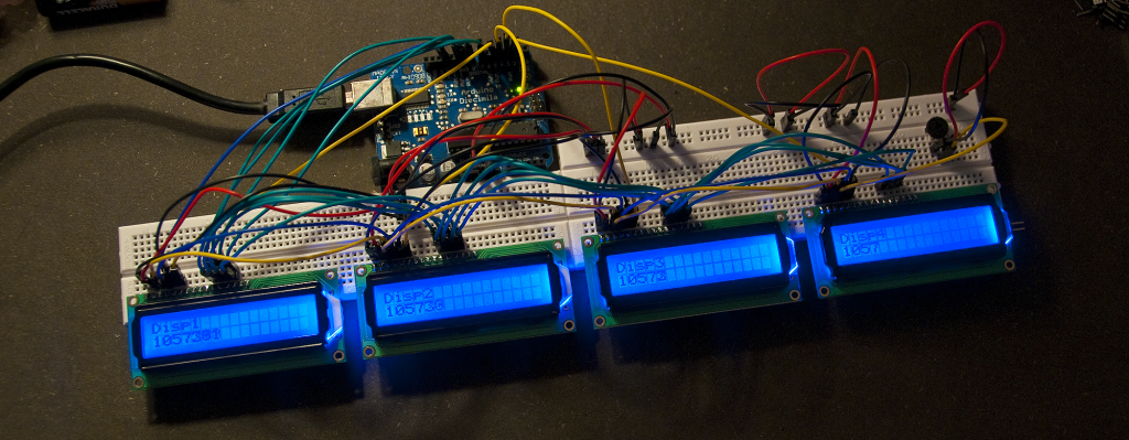
This setup uses a total of 5 shared pins on the Arduino (Data and RS), and then one pin (Enable) for each display.
Below is my modified version of the HelloWorld example from the LiquidCrystal library, that initializes 4 displays and outputs individual content to each display.
1 2 3 4 5 6 7 8 9 10 11 12 13 14 15 16 17 18 19 20 21 22 23 24 25 26 27 28 29 30 31 32 33 34 35 36 37 | // include the library code: #include <LiquidCrystal.h> // initialize the library with the numbers of the interface pins LiquidCrystal lcd1(12, 5, 7, 8, 9, 10); LiquidCrystal lcd2(12, 4, 7, 8, 9, 10); LiquidCrystal lcd3(12, 3, 7, 8, 9, 10); LiquidCrystal lcd4(12, 2, 7, 8, 9, 10); void setup() { // set up the LCD's number of rows and columns: lcd1.begin(16, 2); lcd2.begin(16, 2); lcd3.begin(16, 2); lcd4.begin(16, 2); // Print a message to the LCD. lcd1.print("Disp1"); lcd2.print("Disp2"); lcd3.print("Disp3"); lcd4.print("Disp4"); } void loop() { // set the cursor to column 0, line 1 // (note: line 1 is the second row, since counting begins with 0): lcd1.setCursor(0, 1); lcd2.setCursor(0, 1); lcd3.setCursor(0, 1); lcd4.setCursor(0, 1); // print the number of seconds since reset: lcd1.print(millis()/1); lcd2.print(millis()/10); lcd3.print(millis()/100); lcd4.print(millis()/1000); } |
My test setup is all powered via USB, and the contrast is controlled using a single trim pot, feeding all the displays with the same voltage for the contrast pin (V0).
I’m using pin 7, 8, 9 and 10 on the Arduino for the data lines, pin 12 for RS and pin 2, 3, 4 and 5 for the enable signal for display 1, 2, 3 and 4 respectively, but that’s easy to change if you use some of them for other tasks.
Related posts:
- Custom LCD Characters with Arduino A few days ago I saw a post on Adafruits...
- Programming the LCD I/O Backpack with an Arduino Since the workshop in the beginning of October, there has...
- Learning to program FPGA’s About two months ago a couple of guys from Labitat...
Thanks for this article. I used it to improve my little lap & time slot counter joining an additional display. Now it has one display per lane (it has two).
You can see the old one in this video:
http://www.youtube.com/watch?v=FscmY-A5o_M
The new one is almost ready.
Hi Francisco,
That looks great!
I’m glad that you could use my little “proof of concept” setup documentation for your project.
If you make a video of the next version, feel free to post a comment with a link, I’d love to see that!
/Thomas
thanx for the R&D on the displays. I’m sure this will help a lot of people who want to display more data. Other than having to use multiple serial LCDs; this is just as good.
especially if you have a few parallel LCDs laying around.
thank you for the “LiquidCrystal” multiple display sketch example!! I felt for sure there was a simple way to do this and you found it! Interesting that the official arduino reference site did not have this simple suggestion…but, oh well…
Could you please do a post on hacking a natural display calculator 31-dot × 96-dot LCD screen with an arduino, still keep it looking like a normal calculator
Hi there,
I need to be very efficient using pins for a project I’m working on (I must admit that I’m kind of a newbie). I love what you did, but I had a couple of questions:
1- is it possible that you share how you did the connections (schematics, perhaps)?
2- I have recently read about using an MCP23017 I2C chip to master 1 LCD on 2 Pins, I was wondering in the need for 4 LCDs, if it was possible to be more efficient than your current arrangement?
Thanks in advance for your thoughts.
Hi Gustavo,
If you really need to save pins, one option is to unload the LCD control to a separate chip, eg. another avr… there is even a sketch in the Arduino environment that makes a serially controlled LCD. That sketch could probably be modified a little to be able to control multiple displays and only require a single I/O pin from the main controller to run some UART commands (could probably be soft serial if the hardware serial is occupied).
Using shift registers or I/O expanders is probably also possible, but I haven’t tried it myself.
I hope it helps,
/Thomas
Hi Naadir,
I guess you are talking about the Casio fx350es or something similar, right? Even though it could be fun, I can think of a lot of other projects that I would rather spend time on. Calculators are often custom silicon with all features put together in one “blob” and difficult to interface with. But I do have some graphics display modules that I will probably use in some projects in the future.
Hi Thomas,
I was wondering if you had tried to connect the LCD displays together within the code so that, for example, you could have a message that scrolled across all 4 displays?
I say this because I am currently working on a project using an array of the Nokia 5110 LCD screens and it would be extremely useful if you could give an insight into how you might go about having an array of LCD screens physically but coding them as one large screen.
Cheers,
Ben
Hi Ben,
That is an interesting idea, but not something I have tried, I have treated each display by themselves.
I don’t think the standard library in Arduino would be able to do that, but a few hacks might get close. I would probably look in the direction of letting all displays “see” the complete picture, and then give each a “viewing window” to display. This way, you can also decide to have a little spacing between the viewing windows, since there will be a bit of distance in the real world. Scrolling or circles will look weird if they jump from one display to the next.
If it’s just a uniform scrolling, you might be able to just start each display with a certain time delay, and the same “animation” and you will end up with something that looks like a continued motion, but it’s a hack and not efficient coding
I hope this is useful for you project.
/Thomas