LCD I/O Backpack
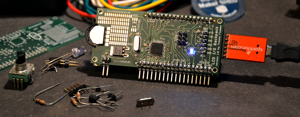
Along with a couple of other guys from my local hackerspace, Labitat, I have designed a little board to be attached on the back of a 16x2 character display (the ones with a 16 pin connector along the top, based on the HD44780 chipset), that can be programmed using the Arduino environment, or of course using C directly as any other Atmel AVR chips.
Design
The design is based on the Pro series of Arduinos made by Sparkfun, so there is no USB onboard, you have to use an FTDI cable or an FTDI Breakout board, or optionally, program the microcontroller directly via the ICSP connection. You can also use the FTDI chip on a regular Arduino, by removing the AVR microcontroller from the board and connecting jumper wires between the FTDI connector on the LCD I/O Backpack and the controller socket on the Arduino board. The last option is a bit of a hack, but it will work if you don’t have any of the other cables.
The PCB is designed with direct connections from the microcontroller to the display using the 4 bit interface. Only 6 pins on the microcontroller are used this way, and we have decided to use the following pins for the display (Arduino pin numbers):
- Pin 7: RS
- Pin 6: Enable
- Pin 5: Data bit 4
- Pin 4: Data bit 5
- Pin 3: Data bit 6
- Pin 2: Data bit 7
These pin numbers are slightly different than the ones used in the examples for the LiquidCrystal library under the Arduino Environment. The reason is that we would like to have the SPI pins available as part of the I/O connections in the bottom.
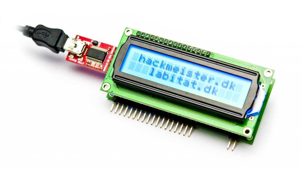
Example code for writing on the display:
#include <LiquidCrystal.h>
LiquidCrystal lcd(7, 6, 5, 4, 3, 2);
void setup()
{
lcd.print("hello, world!");
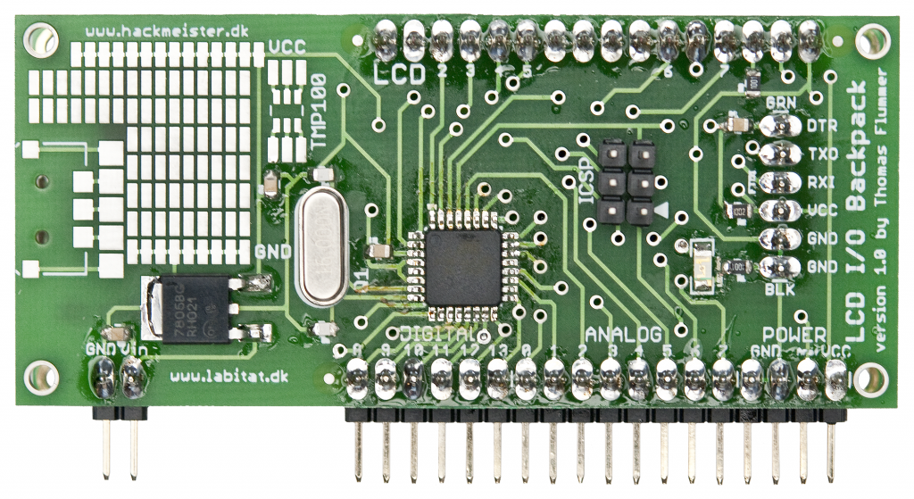
}The PCB is designed with the use of SMD components, only the various pin headers use through hole technology to make them more sturdy.
The project started out when preparing for an electronics workshop in Labitat. We needed a simple board to interface with a temperature sensor and show the result on a display. Initially we just wanted to etch the boards in our lab, but the design ended up as a two layer design with a lot of via holes, so the PCB has been made professionally.
Errata
After the new PCB’s arrived, we have unfortunately found one minor error in the silk screen. It’s the numbers for the Analog pins that has been swapped, so that the pin marked with ‘7’ is actually ‘0’, ‘6’ is actually ‘1’, and so on. Future revisions will most likely keep the pin positions, but have the silkscreen changed, so that code can be easily ported between different revisions of the board.
Different configurations
Early on in the process we decided to design the PCB so that is could be used in various configurations, specifically using different Atmel AVR chips, different frequencies and different voltage levels for the logic.
Below is a list with some of the possible variations:
- The main controller footprint is for a TQFP-32, the same as on the Sparkfun Arduino Pro boards. We selected this also because we have a lot of ATmega8L microcontrollers in Labitat, that we will use for the workshop. If 8KB of flash is too little, there are also larger variations, like the ATmega168 with 16KB flash or the ATmega328 with 32KB flash.
- Depending on what chip you have on the board, either a 8MHz or 16Mhz crystal can be used. You can also use the internal oscillator in the Atmel AVR, keeping the component count at a minimum.
- There is also footprints for a voltage regulator, so that the device (board and LCD display) can be powered directly from a battery (eg. 2 LiPo/LiFe cells or a 9V block battery). Just be carefull when using external power at the same time as connecting an FTDI cable or breakout board, there is no protection that automatically selects the best power source as on the newer Arduinos and consequently the FTDI adapter can be damaged.
- As a bonus, we have added a footprint for an up/down/select button from Sparkfun, that has been positioned on the edge of the board, so that it can be used for menu navigation on the display and since the workshop will focus on temperature measurement, we also decided to add a little breakout area for a Texas Instruments TMP100, a little temperature sensor that interfaces using I2C.
- The left over space on the board has been filled with a small SMD prototyping area.
Configuration for the Labitat workshop
The boards for the electronics workshop at Labitat will have the following configuration (all SMD components mounted, through hole components on the side to be soldered on by the attendees):
- ATmega8L microcontroller (programmed with the Arduino bootloader)
- 8 MHz crystal
- Blue LED connected to pin 13
- 7805 voltage regulator
- Up/Down/Select button
- Support components for the above (0.1uF and 22pF capacitors plus 1K and 10K resistors)
- 16 pin female header for the connection to the display
- 32 pin angled headers for all the other edge connections (Power, I/O and FTDI connection)
Downloads

If you want to make your own board or need a little inspiration to to design a variant, I have included both the schematic and the board files from Cad Soft Eagle. The hardware design is released under Creative Commons BY-SA.
- Schematic file for LCD I/O Backpack 1.0
- Board file for LCD I/O Backpack 1.0
- Sticker with updated pin captions
- Pin descriptions (A4, pdf)
It is definitely possible to etch the board at home! The design is made, so that the PCB doesn’t need to be trough plated. If a trace needs to connect to a pad on the opposite side, I have added a via hole next to the pad, so that the signal is brought to the right side and you avoid soldering components on the “component side”. In the same way, there are no via holes under components, since “home made” via’s aren’t totally flat and the component would not sit correctly.