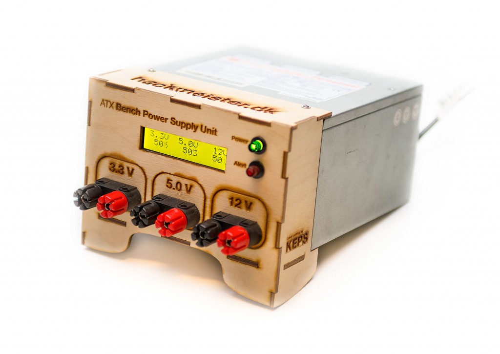
ATX Bench PSU
This project was started a long time ago, and has only slowly progressed, but it’s now ready to be documented and shared with the world.
I’m not the first to use an ATX computer supply top power my DIY projects, but I believe the design I have chosen is great for both advanced users and beginners.
One of the aspects that I have chosen to focus on is the look and feel - I wanted to have something that looked and felt like regular bench equipment, to distinguish it from the birds-nest project that it powers.
Features
The finished PSU has a few basic features, not the most advanced, but adequate for most projects:
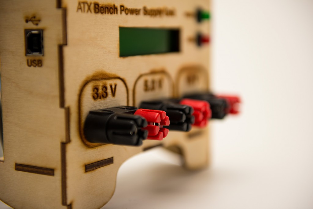
- 3.3V regulated output (usually 30A+)
- 5.0V regulated output (usually 10A+)
- 12.0V regulated output (usually 5A+)
- Current measurement for each output
- Display to show the measurements
- USB interface to output data and update firmware
- Buttons with indicators to turn on/off PSU and show/acknowledge alarms
Design
The original idea was to make a 3D printed part, that attached to one side of the ATX power supply (the one where the wires sticks out) that then could house some electronics and not least the output connectors.
I ran into some problems (wrong tool or incorrect use of the tool), and switched over to a CNC milled or laser cut edition using either plywood or acrylic as the material for the case. I’ll look into designing a part for 3D printing. If you are interested in that, let me know in the comments and we can maybe work together on a design.
Lasercutting also opens up for additional decoration via laser engraving, which the current prototype uses. It’s a bit slow to do the engraving, but gives the PSU a nice finish and no need to add information afterwards.
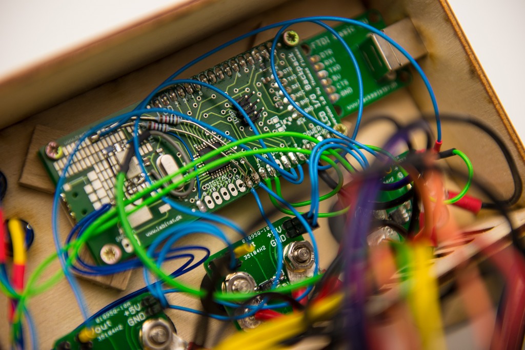
Electronics
The electronics are based on the LCD I/O Backpack, with a custom FTDI board for USB interface and 3 separate current measurement boards mounted on the back of the output binding posts.
The choice of electronics are mainly because of accessibility, other boards can also be used, but slight changes in cabinet size might be needed, as it’s a bit crammed already.
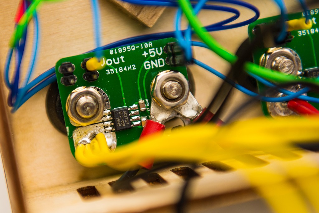
The current sensing boards are based on the Allegro ACS712 hall effect based current sensor each having an analog output that is sent to an analog input of the Arduino based LCD I/O Backpack. These sensors are very close to linear and hence very easy to use on the coding side. I have made a few tests with a computer controlled DC load and can confirm this linearity.
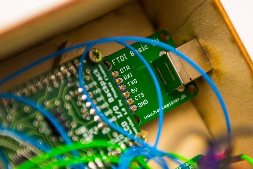
The USB interface is nothing but a stripped down FTDI interface based on the FTDI FT232RL. The major difference from other FTDI boards is the full size USB-B socket that is slightly off axis to compensate for the off axis connectors on the LCD I/O Backpack, so that everything lines up nicely on the outside of the box.
To make the device useful, an optocoupler has been added to turn on/off the ATX power supply, and similarly a few parts have been added to control the backlight on the LCD, to make it look “off” when not running. The control electronics are powered from the “always on” permanent 5V output that the can easily power the LCD I/O Backpack. This setup isn’t ideal, but it’s pretty simple to implement.
The buttons and indicator light are simply connected to some spare I/O with a few resistors in series to keep it running smoothly.
To control the state of the ATX PSU, an optocoupler is added to an output on the LCD I/O Backpack.
Software
The software is currently very basic, I haven’t even converted the raw output from the analog inputs to readable current values, but it should be relatively simple to have both nice readouts, logging output via USB and maybe some alarms (a buzzer would also be interesting here).
The code below is a simple test controller, made for testing the different pieces. It needs a bit of finishing to reach the same polished level as the rest.
/*
  ATX Bench Power Supply Unit Controller
  -----------------------------------------------------------------
  by Thomas Flummer, hackmeister.dk

 */

// include the library code:
#include <LiquidCrystal.h>

// initialize the library with the numbers of the interface pins
LiquidCrystal lcd(7, 6, 5, 4, 3, 2);

const int powerPin = 8;
const int powerSwitchPin = A7;
const int alertSwitchPin = A6;
const int powerLEDPin = A5;
const int alertLEDPin = A4;
boolean powerState = false;
boolean alertState = false;

void setup() {
  // Power pin setup
  pinMode(powerPin, OUTPUT);
  pinMode(powerLEDPin, OUTPUT);
  pinMode(alertLEDPin, OUTPUT);
  digitalWrite(powerLEDPin, LOW);
  digitalWrite(alertLEDPin, LOW);

  // set up the LCD's number of columns and rows:
  lcd.begin(16, 2);
  // Print a message to the LCD.
  lcd.print("");
}

void loop() {
  int powerSwitch = analogRead(powerSwitchPin);
  if(powerSwitch < 100)
  {
    if(powerState)
    {
      digitalWrite(powerPin, LOW);
      digitalWrite(powerLEDPin, LOW);
      powerState = false;
      lcd.setCursor(0, 0);
      lcd.print("                ");
      lcd.setCursor(0, 1);
      lcd.print(" Standby...     ");
    }
    else
    {
      digitalWrite(powerPin, HIGH);
      digitalWrite(powerLEDPin, HIGH);
      powerState = true;
      lcd.setCursor(0, 0);
      lcd.print(" ATX Bench PSU  ");
      lcd.setCursor(0, 1);
      lcd.print(" Booting...     ");
      delay(2000);
    }
    delay(500);
  }

  int alertSwitch = analogRead(alertSwitchPin);
  if(alertSwitch < 100)
  {
    if(alertState)
    {
      digitalWrite(alertLEDPin, LOW);
      alertState = false;
    }
    else
    {
      digitalWrite(alertLEDPin, HIGH);
      alertState = true;
    }
    delay(500);
  }

  if(powerState)
  {
    /* if turned on */
    lcd.setCursor(0, 0);
    lcd.print("3.3V  5.0V   12V");


    int current3v3 = analogRead(0);
    int current5v0 = analogRead(1);
    int current12v = analogRead(2);

    lcd.setCursor(0, 1);
    lcd.print(" ");
    lcd.print(current3v3);
    lcd.print("   ");
    lcd.print(current5v0);
    lcd.print("   ");
    lcd.print(current12v);
    lcd.print("  ");
  }
  delay(100);
}
If you have ideas or want to help, you are very welcome to let me know in the comments.
Download
 There is a bunch of different parts to this projects, both mechanical parts for the case and electronics boards. Schematic and the board files are in Cad Soft Eagle format, mechanical parts in Adobe Illustrator EPS and PDF. The hardware design is released under Creative Commons BY-SA.
- LCD I/O Backpack (see separate page with schematics and board layout)
- Custom FTDI interface board (Schematic and Board layout)
- Current sensor board (Schematic and Board layout)
- Drawings with the case meant for laser cutting and engraving (3 mm material thickness) (EPS file zipped up or PDF file)