Alternative programming cable for LCD I/O Backpack
A little over a month ago, I saw a post at Let’s Make Robots about making your own “FTDI” cable equivalent.
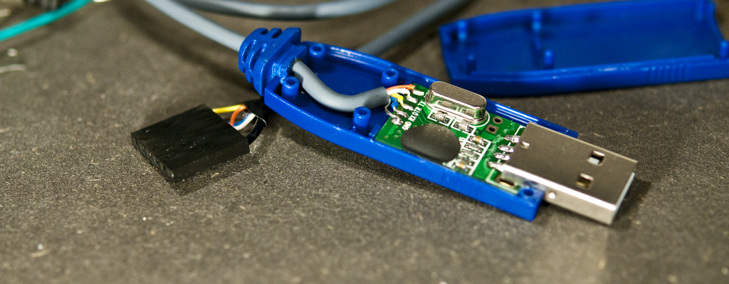
The basis for this project is a cheap copy of a CA-42 interface cable for Nokia cellphones sold by DealExtreme. There are a lot of these cables, and they all look alike, but this one has something special: It’s hacker friendly!
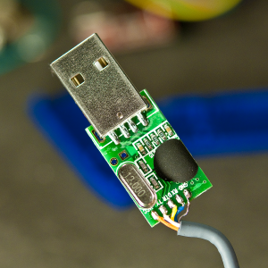
The oversized USB connector not only holds all the electronics, but it’s made with two plastic pieces that can be separated easily using a little screwdriver or knife and not least be put together again afterwards without any noticeable trace.
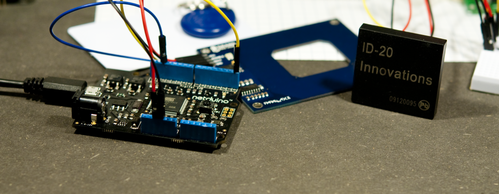
When I found this, I ordered a few right away, since these would be ideal for programming the LCD I/O Backpack or any other Arduino in the “Pro” series for that matter.
When I got the cable, modifying it went very smooth, first desoldering the existing cable and then soldering on a new cable, recycled from an old mouse. The cable needs at least 5 leads, one for GND, one for VCC, one for RX, one for TX and finally, one for DTR, so that the AVR chip can be reset automatically by the programming software. The cable I use has 4 wires and a shield, which I used for GND.
- GND: Shield
- RX: Blue
- DTR: Yellow
- TX: White
- VCC: Orange
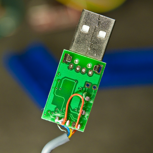
There was a few small red wires soldered to the PCB, and I removed one and left the other one in place as illustrated on the image to right, showing the back of the PCB that goes in the USB connector housing.
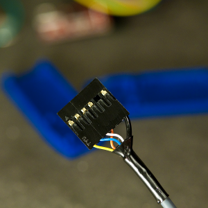
In the other end of the cable I crimped on female header pins and mounted them in a 6 pin header assembly in the same order as used with the FTDI cables and adapters.
Another advantage to making your own cable is that you can make it as long or short as you like (within reason of course). I made mine about 50 cm (1.5 feet) since most of the time, I use it right next to my laptop, and a long wire is just in the way.
- DTR: Yellow
- RX: Blue
- TX: White
- VCC: Orange
- GND: Not connected
- GND: Shield
Remember, RX and TX on the cable side is crossed compared to the connections on the LCD I/O Backpack and other Arduinos.
This cable uses the Prolific PL2303 chip, and the driver is available in the Prolific website Download section. When the driver for your OS is installed and working, this cable will show up as a virtual serial port very much like the FTDI cables. On Windows you will see very little difference when selecting the port, it will be COM5, COM6 or similar. On Mac and Linux, the name will be a little different, most likely something similar to /dev/tty.PL2303-00001004, maybe with different numbers at the end of the name.
In the Arduino environment, you just select the port and use it like if you connected any other cable, adapter or a full Arduino.
The only thing I’m a little unsure about is how much current you can draw from this cable, but I have successfully been running an LCD I/O Backpack and a display, without any problems.